Neutral earthing resistors – Neutral grounding resistors
Neutral earthing resistors or neutral grounding resistors are used to protect transformers, generators and distribution networks by limiting the fault current in event of an earth fault. The earthing resistor is based on a standard design with large flexibility for different installations. Long life and a minimum of maintenance have highest priority.
Standard
There are two Industrial standards specifically covering Neutral Earthing Resistors. The European standard is IEC60076-25:2023 “Power Transformers, Neutral Grounding Resistors” and the more established American standard IEEE-C57-32a (2020) “Standard for Requirements, Terminology, and Test Procedures for Neutral Grounding Devices”. We can supply earthing resistors according to both.
Other applicable standards are IEC60529 for ingress protection and IEC60071 for insulation coordination.
Resistor materials
The resistance alloys used are high temperature stainless steels capable of withstanding temperature excursions to 1000°C whilst retaining their strength. It guarantees long and reliable life even if the temperatures exceed 760°C, specified by ANSI IEEE C57.32a and IEC60076-25. Neutral earthing resistors designed for operation to higher temperatures require less active mass, resulting in more compact and economical designs.
The resistance alloys used increase in resistance as they get hotter. ANSI IEEE C57.32a states that the resistance change of an neutral earthing resistor should not change by more than 67% from cold value over the temperature range. This is to ensure that the final fault current is sufficiently high to allow protective circuitry to operate as intended. IEC60076-25 does not specify any resistance change with temperature, however there is an advisory comment in the standard that maximum resistance change should be selected based on the network and protection system.
Connection time
Today’s most common connection time is 10 s. This gives a good safety margin since most earth faults are detected and switched off in less than 1 s. Earlier longer connection times were specified, mainly due to the use of liquid cooled resistors. The shorter connection time, the more compact design.
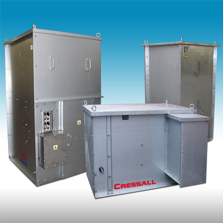
Enclosure
Most earthing resistors are supplied enclosed for outdoor use, ingress protection is normally IP23 or IP54, up to IP56 on request. The enclosure is manufactured of pre-galvanised or hot-dipped galvanised steel or of stainless steel type AISI 304/316L. Some resistors are supplied as open type, to be built-in in switchgear or similar.
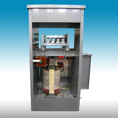
Complete earthing systems
Earthing resistors connected to transformers or generators are most commonly used together with other components like isolators, vacuum contactors, current and voltage transformers. They are often located in the switchgear. One alternative is to combine these with the earthing resistor and form a complete earthing system.
There are many advantages to instead combine them with the earthing resistor, which will form a complete earthing system. Above all, installation and commissioning are simplified when the earthing system is supplied as one connected and factory tested unit.
Common combinations are resistors with disconnectors, manually operated isolators or vacuum contactors as well as current and voltage transformers for metering.
The resistor can also be combined with dry type transformers, Zn type or a single phase transformer with earthing resistor on the low voltage side.
Presentation, references
For more information, contact one of our
PRODUCT SPECIALISTS